Distortion Grid — How To
This guide is the result of many years of experience gained by us and our colleagues while working on film sets and vfx studios.
Here, we provide the most comprehensive and step-by-step instructions for shooting Distortion grids for various types of cameras and lenses.
Additionally, we provide a file naming template that corresponds to industry standards.

Preparation
-
Firstly, you need a grid – you can create it by yourself, buy it from us, rent it, or in some cases even display it on your monitor screen.
-
Firstly, you need a grid – you can create it by yourself, buy it from us, rent it, or in some cases even display it on your monitor screen.
-
There are no ideal grid parameters – it all depends on the camera and the used lens.
We have chosen a size of 62x120cm with a grid spacing of 15mm.

-
We strongly do not recommend you to use grids with reduced grid scale in the center – in some software, such as 3DEqualizer, this complicates automatic grid detection.
-
We strongly do not recommend you to use grids with reduced grid scale in the center – in some software, such as 3DEqualizer, this complicates automatic grid detection.

-
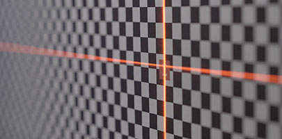
Securely fasten the grid vertically maintaining the horizon. It’s important to make sure that the surface of the grid is perfectly flat and free from waves, wrinkles, bends, or any other deformations.
-
Securely fasten the grid vertically maintaining the horizon. It’s important to make sure that the surface of the grid is perfectly flat and free from waves, wrinkles, bends, or any other deformations.
-
Make a flat soft lighting setup, as highlights and strong lighting variations can complicate the automatic grid detection.
-
Make a flat soft lighting setup, as highlights and strong lighting variations can complicate the automatic grid detection.
Camera Setup
Choose the frame format that uses the maximum area of your camera sensor during filming.
If you are unsure which format to choose, shoot in Open Gate.

-
We recommend to shoot grids after the main footages has been filmed – this is necessary to know in which formats the shooting was done, because the format affects which part of the sensor is used.
-
If you’re not sure about the resolution you need to shoot in, or if Distortion grids are being shot before the shooting period begins, then shoot in Open Gate (a format that uses the full sensor size). Matchmove artists will find it more challenging to work with this material, but you will be certain that you have captured all the necessary information. Starting from version 7.1, 3DEqualizer introduced a tool for adapting grids to the required format. For users of earlier versions, we have prepared our own tool.
-
It is important to note that higher resolution does not always equal a larger sensor size – we recommend checking the information on the manufacturer’s website of your camera or using the website vfxcamdb.com (don’t forget to donate to its author).
-
It is important to note that higher resolution does not always equal a larger sensor size – we recommend checking the information on the manufacturer’s website of your camera or using the website vfxcamdb.com (don’t forget to donate to its author).
Lens setup
Install the lens with the minimum focal length.
If using a zoom lens, set it to the minimum focal length.
Place the camera so that its optical axis is perpendicular to the surface of the Distortion grid.
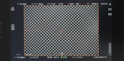
Make sure that the edges of the frame are completely covered with a chess pattern.
-
Double-check with the camera operator that the coverage is based on the effective sensor area – not the internal frame that can be set in the display settings
-
Don’t try to fit the entire grid within the frame – let it extend beyond its boundaries if necessary.
Сlose the iris to its maximum value.
This is necessary in order to achieve the maximum depth of field, which will be required when changing the focus distance in the next steps.
-
Shooting Distortion grids for different focus distances is important because when adjusting the focus ring, the ‘lens breathing’ effect occurs, which also affects its distortion, especially pronounced in anamorphic lenses.
-
Now you understand that it’s important to shoot focus distance AND gather this information on the set for each shoot, because only together they will work correctly.
-
Most likely, a closed iris will significantly darken your image, therefore:
Reduce the FPS to the minimum value.
Set the shutter speed to the maximum (shutter 360).
If necessary, increase the ISO.
-
After that, we recommend turning the focusing ring to make sure that the grid is in focus and covers all of the frame at the all focus distance values.
Before The Next Steps
Let’s go over again what focal length is and what focus distance is:
Let’s go over again what focal length is and what focus distance is:
-
Focal length is the distance from the optical center of the lens to the camera sensor.
-
The focus distance is the distance from the camera sensor to the object that you want to get in focus.
Next
Set the minimum focus distance on the lens.
Ensure that the grid is in focus.
Next, record the following information on a sheet of paper:
-
Camera model
-
Frame format (shooting resolution)
-
Focal length
-
Focus distance
Shooting
Shoot the frame.

-
Attach a sheet to the grid and press REC.
-
If you are recording at a rate of 1 FPS, then after a couple of seconds, remove the sheet from the frame and, making sure that the grid image is evenly illuminated and without shadows, stop recording.
-
For your convenience, magnetic stickers are included with XYZ.Grids to record this information, which you do not need to remove from the frame.
After that, change the focus distance.
-
The step is determined independently based on your needs: the smaller the step, the more accurate the lens distortion profile will be, and the more time it will take to shoot.
-
For example: Hawk V-Lite Anamorphic 28mm (minimal focus distance 0.8m): 80 – 100 – 130 – 180 – 200 – 250 – 350 – 450 – 600 – 800 – 1500 – ထ
-
ATLAS 32mm (minimal focus distance 0.55m): 55 – 65 – 75 – 85 – 100 – 120 – 140 – 200 – 250 – 300 – 450 – 1000 – ထ
-
As you can see, the change in focus distance is non-linear. This is because the shorter the distance, the more the distortion parameters change Try to maintain a similar dependency as in our example.
After reaching the “infinity” focus distance value, install the next lens and repeat steps 9–14.
-
Please remember that we perform the shooting from a shorter to a longer focal distance lens. In that case we will get a slightly larger grid spacing in the frame, but in most cases this is enough – it helps to minimize camera movements.
If we use zoom lenses, the algorithm is similar to shooting a Distortion grid for fixed focal length lenses, only instead of changing the lens, we rotate the focus distance adjustment ring and repeat steps 9–14.
-
It is important to note that the non-linear dependence, as with the focus distance, no longer works here, so we take steps based on classical focal length values: 8 – 14 – 18 – 24 – 32 – 35 – 50 – 65 – 80 – 100 – 135 – 140 – 200 – 300 – 400 – 600
-
In some cases, when the focus distance range does not allow you to move the camera far enough away from the grid, you may get a large grid size in the frame. For this you need to use a grid with halved grid spacing. If you are using XYZ.Grid, just magnetize an additional mini grid on top of the main one. The principle here is the same – the new grid should completely overlap the frame.

Great! If you have followed our recommendations, you have got great grids, which will be very easy and comfortable to work with.
Additional
Lens Data System
For the most accurate lens distortion workflow during camera tracking and compositing, we recommend using the Lens Data System (LDS), which writes not only the focal length but also focus distance values into the metadata.
This allows to apply of dynamic distortion correction within a single shot, even if focus adjustments were made. Zoom lenses without this feature make it practically impossible to use the captured grids because we can only be certain about the extreme values of the focal length, as they are mechanically limited. Precisely setting intermediate values, such as 50mm, on such a lens is practically unrealizable.
Better to shoot Distortion grids at the end, when you know all the lenses and camera formats that were used.
Naming of your working files
It is also important to follow the proper naming of your working files.
The industry standard looks like this:
[camera_model]_[resolution]_[lens_model]_[focal_length]_[focus_distance].jpg
arri_alexa_mini_2880x2160_hawk_class_x_120mm_1.2m.jpg
Different Grid and Footage resolutions
If you shoot Distortion grids in Open Gate and received a shot for tracking in a different resolution, follow these steps:
1. Divide the physical width and height of the sensor (in mm or inches) used for the tracking shot, by the physical width and height of the sensor for the Open Gate format.
2. Obtain 2 coefficients.
3. Multiply the width and height in pixels of your Distortion grid by the obtained coefficients, and crop your grid to the resulting pixel values.
4. Scale the resulting image to the format of your tracking shot and save it.
Please notice again that for many cameras the resolution in pixels does not correspond to the sensor size (some cameras may record in different resolutions using the same sensor size).
Example for ARRI Alexa LF camera:
LF Open Gate Mode:
4448 x 3096 | 36.70 mm x 25.54 mm
LF 16:9 Mode:
3840 x 2160 | 31.68 mm x 17.82 mm
2048 x 1152 | 31.68 mm x 17.82 mm
1920 x 1080 | 31.68 mm x 17.82 mm
Suppose the shot was taken in 1920 x 1080, and the grid in 4448 x 3096.
Divide 31.68 mm x 17.82 mm by 36.70 mm x 25.54 mm.
Obtain a crop coefficient of 0.863215258855586 х 0.697729052466719.
Multiply 4448 x 3096 by the crop coefficient.
Obtain 3840 x 2160.
Crop our grid to this value and then scale it to 1920 x 1080.
Done!
Video tutorial and our tool for crop distortion grids:
For your convenience, we have prepared a lens distortion database for the most popular models.
