If you’ve ever wanted to transfer planar tracking or PowerMesh data from Mocha — now you can👌
The video shows how to install and use the tool.
If you’ve ever wanted to transfer planar tracking or PowerMesh data from Mocha — now you can👌
The video shows how to install and use the tool.


In this series of tests, we will answer the most popular questions about camera tracking that arise among CG artists.

Atlas Orion 50mm

Atlas Orion 65mm

Sigma 50mm

Ultra prime 20mm – 3х

Ultra prime 32mm – 3х

Arri SP 125mm

Cooke S4 18mm

Cooke S4 25mm

Cooke S7i 100mm
As you can see the lenses turned out to be largely interchangeable. While the distortion curves showed some minor differences, their overall behavior was remarkably consistent. The solve errors practically identical.
That means we can reliably use a distortion profile from any lens within the same model range and focal length.
Curious to dive deeper or run your own analysis?
All detailed data and test materials are available for download
Easily transfer Camera, Points and Geo between 3DEqualizer, Nuke and Blender.
The most accurate and detailed camera sensor database available today.
In this series of tests, we will answer the most popular questions about camera tracking that arise among CG artists.
As you can see, differences in Angle of View between these cameras, when sensor areas are matched, are minimal. The slight discrepancies observed are mostly due to our practical limitations in positioning sensors precisely rather than actual flange distance variations.
This shows that each mount standard maintains a consistent flange distance across all compatible cameras, even when adapters are used.
This means, to shoot a distortion grid, we can safely choose any camera with a larger sensor size than the one used for our tracked footage. After capturing, we simply crop the grid footage to match the sensor dimensions of our main camera.
Also you can download distortion grids below for self checkup.
In this series of tests, we will answer the most popular questions about camera tracking that arise among CG artists.
Reminder: It is crucial to crop based on the sensor size ratio, not the pixel aspect ratio.
Most cameras have varying pixel densities per millimeter of the sensor.
Some cameras also perform downscaling – reducing the resolution of the digital image while maintaining proportions. This is done to ensure the required recording speed, for example, when shooting in slow motion (high frame rate). downscaling ≠ crop!
The formula for calculating the crop factor based on width is:

The formula for calculating the crop factor based on height is:

For width:

For heigth:

Real camera lenses have distortion, but virtual cameras in 3D software don’t, which leads to renders with straight lines.
To blend CG with real footage, you need to apply lens distortion. This can create empty edges on the render.
Overscan helps solve this by rendering with extra margin, ensuring that after distortion, the frame remains complete.
In this guide, we’ll show how to apply overscan in various 3D software tools.
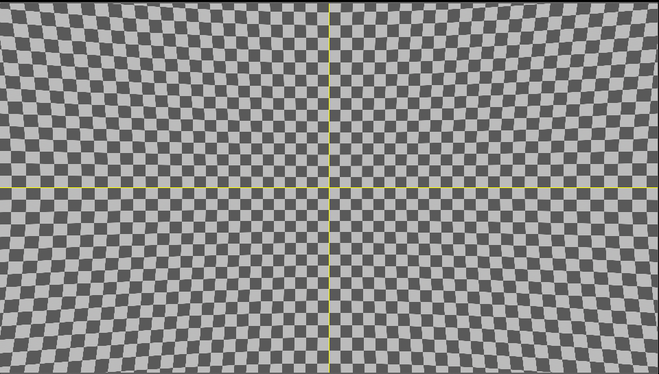
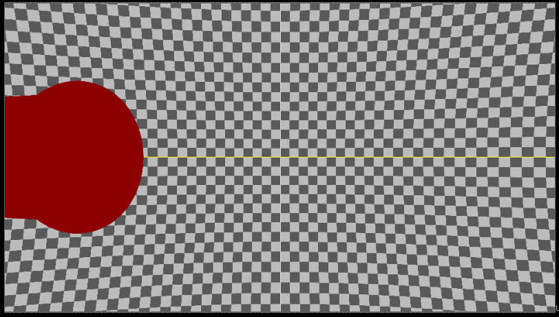
Screenshot 1 shows a grid with lens distortion. You can see how straight lines are distorted at the edges.

Let’s assume that the CG object is at the edge of the frame (screenshot 2)

In order for a CG object to render correctly in the footage, you must apply distortion to it that corresponds to the lens.
In this case, after distortion is applied, the CG part will be stretched and “tiling” will occur.

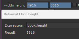
To find out which overscan is needed, you can look at the bounding box settings in Nuke.
The dotted box shows how much the image extends beyond the edges.

You can also create a reformat node with these parameters:


It is important to note that overscan is not just an increase in render resolution.
It is an increase in the field of view of the camera + an increase in the resolution of the CG renderer.
To create an overscan in Cinema 4D there is a handy xpresso script that will create a new camera with overscan values.
To do this, add Canvassizecamera to your project and select the xpresso tag.

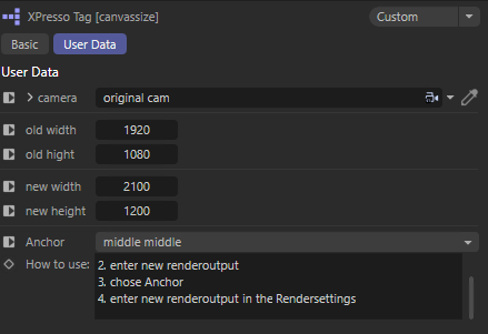
Next, in the camera parameter you need to create a link to your 3D camera.
After that specify old resolution and new resolution with overscan and then make the Canvassizecamera camera active.
Don’t forget to specify the new resolution in the project render settings.

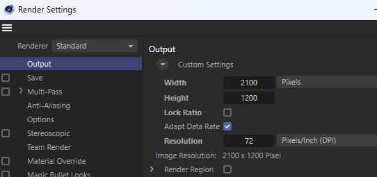
As a result, the renderer will have an increased FoV.
To get overscan you need to go to the camera settings, View tab and then in the Resulution field specify how many percent overscan is needed.

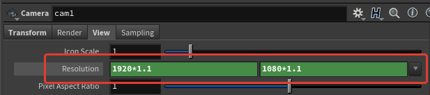
Then specify a new value in the Screen Window Size field. In the case of the example it is 1.1

When rendering, select the desired camera with the applied modifications and do not change the resolution in the render settings.
To specify overscan parameters, go to the render settings, Image Output → Aspect Ratio tab. In the Data Window NDC field specify the required parameters.
For example, an overscan of 10% will have the following parameters: -0.1, -0.1, 1.1, 1.1

Note that the first two fields must have negative values.
Houdini Docs:
The default is 0, 0, 1, 1 (no cropping). Note that you can use negative values.
For example, -0.1, -0.1, 1.1, 1.1 will give you 10% overscan on each side.
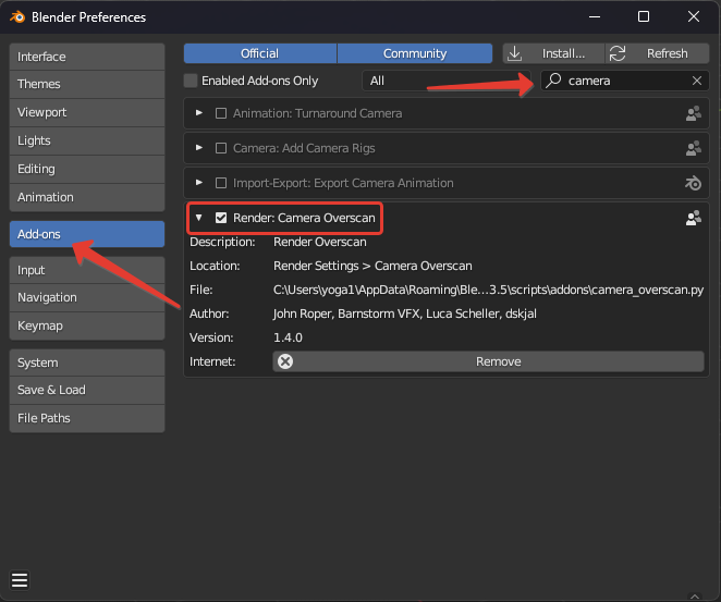
In order to apply overscan in Blender it is necessary to install Addon.
The addon has been tested in program version 3.5.1.
Download Camera Overscan Script (Python)
Download Overscan Background Popover Script (Python)
Place both files in the following path:
Windows: C:\Users\{USER}\AppData\Roaming\Blender Foundation\Blender\3.5\scripts\addons
Linux: HOME/.config/blender/3.5/scripts/addons
macOS: /Users/$USER/Library/Application Support/Blender/3.5/scripts/addons
Then run the program, go into the settings and enable addons:

After that, an additional button will appear in the viewer, which will open the menu.

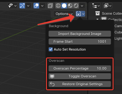
Overscan Percentage – specify the percentage of overscan;
Toggle Overscan – increases overscan by the specified percentage;
Restrore Original Settings – returns original parameters.
To set an overscan in Maya, regardless of the renderer, you need to go into the render settings:

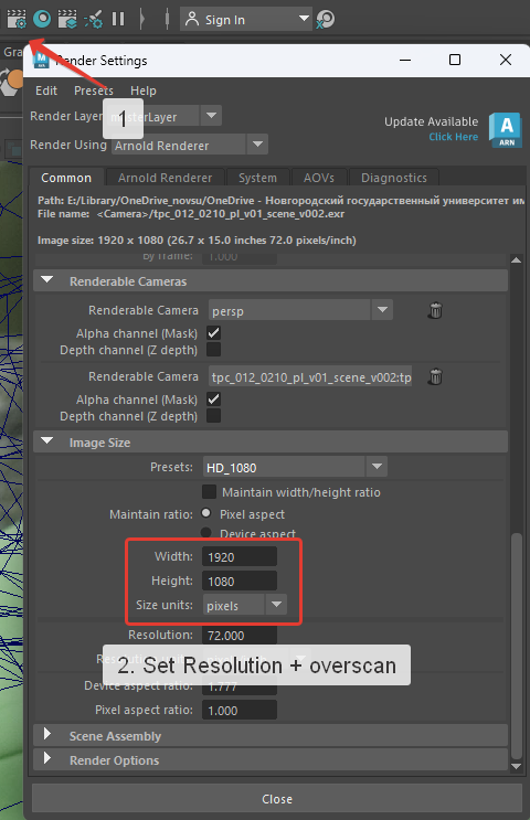
Specify a new resolution with overscan. For example, if you need 10% overscan, then the new resolution for 1920×1080 will be 2112×1188.
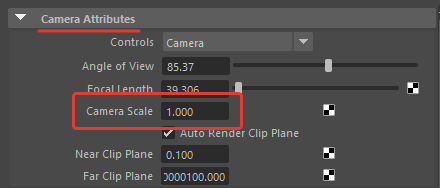
Then, in Outliner, select the required camera and in the camera attributes, change the Camera Scale parameter by specifying the required FoV increase of the camera. For example, at 10% you should specify 1.1.

Now you understand the purpose of overscan and how to work with it in various 3D packages.
For convenience, you can use a ⚙️🔧 script for Nuke that automates the process of creating overscan and preparing nodes for its further use.
File naming in a project is a crucial aspect that helps maintain order and facilitates working with files at different stages of the project. File names should be standardized so that any artist in the team understands exactly what each file contains.
In this guide, we will explore the fundamental rules and recommendations for creating consistent file names, as well as discuss methods for organizing projects based on the practices of our studio.
Thus, the general path of a shot will be: Drive/Matchmove_machine/Project_Name/Shot_Number/ShotNumber_v001
After setting up the project structure, we begin our work.
During the work process, all files are saved in the “_v001” folder. Here are the main types of files you will encounter:

Geometry naming nuances:
Special attention should be paid to version numbering.
It is important to pay special attention to version numbering.
We never increment the version number on our own. Even if we create internal versions during our work or receive comments from the lead, the project version only changes when we receive comments from the client. Only then do we create a new version folder “_v002” within the project folder and save all the files under the second version.
There should not be a situation where the export folder with version 001 contains files with higher version numbers (shotnumber_track_v004_3_(2).3de).
To save intermediate versions, when you want to fix the result and try a different approach, you can create a “backup” folder within the version folder. This folder should be used to store various working versions. However, in such cases, it is important to be careful not to get confused, not to send this folder during the export to FTP, and not to send an incorrect version.
All of this is necessary to avoid confusion between the client’s and our versions during the work process. When we start working on a shot, the client expects the first version (v001) from us. If a situation arises where corrections or additions are needed, then the second version (v002) is expected from us, and so on. This ensures clear naming and understanding from all sides.
Before uploading the result, we check how our folder with files looks. We ensure that if the working version is 001, then all files have this version. We look for typos in the names.
The export requirements are usually specified and pinned in the project’s work chat and may vary. We carefully read the chat and ensure that we have all the files and there are no extras. The export location is also specified and pinned in the project’s work chat.

Note: If a situation arises where corrections are needed and a new version is created, then we upload all files with the v002 suffix. Even if these files have not been changed. It should not be the case that, for example, the scene is the second version, but the geometry and undistort are the first. This can lead to questions about whether the correct files have been uploaded and whether the required changes have been made. Explanations like “take the scene from the third version, the geometry of the second, and the undistort from the first” look confusing to everyone.
Therefore, we eliminate these questions by uploading everything in the new version.
It is important to check yourself every time before and after uploading the result, regardless of how confident you are and how automatic the process is. Mistakes, typos, and oversights can happen to anyone, so it is not difficult to double-check the number of uploaded and required files, check the names, and check the version.
Welcome to our comprehensive step-by-step guide on how to shoot distortion grids! In this video, we will walk you through the entire process, ensuring you capture precise and accurate distortion grids for your projects.
Discover the essential techniques and tips for setting up your shots, avoiding common pitfalls, and achieving optimal results. We’ll highlight the most frequent mistakes made during the shooting process and provide valuable insights on how to correct them.
Additionally, you can find links to useful materials and resources in the description below, which will further aid you in mastering the art of shooting distortion grids.
Watch the video to enhance your skills and ensure your distortion grid captures are flawless every time!
Explore our complete Distortion Grid shooting guide with detailed instructions for different cameras and lenses, including proper file naming schemes according to industry standards. Based on experience from major VFX studios.